Monday, December 10, 2012

Dwelling Block Layout Plan

This plan is of the uppermost level of the (U.C) underground community (the 7th level). As it is underground all traffic into and out of the underground community is done by the stairs and lifts, located at the four corners of the community. 

This plan shows the block layout of the dwellings within the underground community. Blocks are divided into 12 x 12m grids with some block becoming unusual shapes due to the pathways. The 12 x 12m blocks can be divided into smaller blocks (as seen within the top level of the sections which are 12 x 6m blocks) or dwellings can occupy multiple levels through removing or altering the square concrete cut outs (Can also see this within the sections).


Plan View Concrete Cut Out

This plan shows the concrete cut out grid formation that spreads over each level. The concrete cut outs sit on a 6 x 6m grid which sit within the 12 x 12m grid of the dwelling block layout. All of these concrete 'squares' can be removed to allow for more light and ventilation to circulate through the spaces. The squares can also be removed or altered so a resident is able to occupy multiple levels. This can be seen within the sections. 


Section 1:100 (A - A)

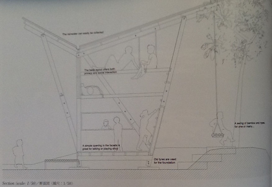
This section shows the various dwelling configurations and the light shaft penetrating the underground community. The section also includes the various concrete squares that have been removed or altered to allow for multi level interaction and the squares left in place to allow for more dwellings. 


Refer to Dwelling block layout plans and concrete cut out plans for placement of sections.

Lift shafts - The lift shafts are located in the four corners of the underground community and are directly adjacent to the stair shafts. these lifts are approximately 5 x 5m and allow people and equipment movement for all levels. These lifts go to all 7 levels and also provide access to the ground level above for people to enter and leave the site.

Backyards - These spaces are private spaces and located adjacent to peoples dwellings. Rather than fill their whole space with the dwelling, people may choose to sacrifice some internal space and have an external or backyard space that acts like a real backyard would above ground. These spaces are fitted with u.v lights and the services ducts allows residents to water their gardens. These spaces would suit families, providing space for children to play in, or for somebody who likes gardening or keeping their own yard. It also provides unique spaces and adds to the aesthetic of the community.  

Concrete squares - These squares are seen on the concrete square grid plan. The layout alternates over each level so the level above can be directly accessed. These concrete squares can be left in to separate the access to adjacent floors and create more dwellings, removed to allow for lighting and cross floor ventilation and altered to create multi level dwellings or provide access around the levels. 

Green Spaces - The green spaces are located within the four large light shafts and in the spaces directly surrounding the shafts. As is visible in the section above, plants and grass are able to grow in these spaces and various concrete squares can be removed to allow plants to grow through multiple levels. Plants have been bio engineered and are able to grow in much smaller amounts of soil while small trees can grow healthily in small planter boxes with the required nutrients. The bio engineering allows them to thrive in less soil with less water and light and to chosen limited heights. 

Light Shafts - There are four light shafts throughout the underground community (can be seen in the plans). These light shafts are various shapes and sizes and enable lighting and ventilation of the spaces. They also contain vegetation within and surrounding to clean the air and create relaxing environments throughout the underground community. 

Water Storage Body - Any run off or rain that falls into the space is captured and moved into the water storage body. All water is constantly filtered in the service cube (can see this in older posts) before moving into the water storage body. This water is kept clean and provides water for all needs of the underground community. Once the water is used all grey and black water is again filtered through a number of processes before storage once again. 


This section has incorporated many of the different exemplar 1:100 sections used. It was very important within this section to include the right amount of detail, leaving the finer information to the 1:50 section but including the major features to show how the underground community worked.


Section 1:50 (B - B)

This 1:50 section shows the intended use of the spaces within the underground community and their spatial qualities. As is visible from this section there are a number of dwellings within this section with many different shapes, sizes and over a number of levels. Some of the different configurations can be seen in previous semester posts and some different configurations can be seen in the sections. There are no set or pre arranged configurations, as a new resident will decide what sort of configuration they would like before they move in. These will either be in one small block, across a number of blocks or on a number different floors by removing or altering the concrete cut out squares.

I have chosen not to include the lift shaft within this section as it would have meant leaving out the light shaft which is a major component of the underground community (Seen in the section below). The 1:50 section was not big enough to include both and therefore I chose to include this area rather than the lift. This is because the lift shaft is seen in the 1:100 section and very little extra detail would have been seen in the 1:50 section. 


U.V Lights - The U.V lights are fitted in all of the external or 'Backyard' spaces. These lights provide the light for the plants to grow in spaces that are not reached by the sun. Within these external spaces, the light above would seem similar to being outside, with similar brightness and heat. These lights are powered by special U.V solar panels located on the roof and around the interior walls of the car recycling centre.

Real Windows are available to people living adjacent to the pathways or green spaces. These Windows replace the mimicking windows in these places and allow direct sight of the outside and more ventilation if the windows are open.

While my 1:50 section may not look very similar to some of the exemplar sections I used, the main things I have brought into my sections are more of the basic ideas and techniques like level of detail, line work and showing the quality of spaces. I have shown the quality of spaces and how they are used by incorporating furniture and items in the dwellings like how it could appear. I have also tried to show another perspective of the quality of spaces in the other 1:50 section seen below. 

I have also tried to recreate some of the colour and tone techniques that I found in some of the other exemplar drawings. Whilst I could not recreate the styles exactly, I used them as a starting point and used my own style. I think the level of detail I have included in my 1:50 is similar to the 1:50 exemplar sections I used and I think by including the various objects and details, it is easy to understand the spaces and their qualities.


Section 1:50 - (B - B) Lighting within Underground community

This section gives a different view of the quality of the spaces.  Obviously as it is an underground community, no spaces would receive light without artificial lighting. Because there are four light shafts penetrating the space there is now a lot of natural light surrounding those shafts. Therefore artificial lighting will still be required to light the spaces further away from the shafts. 

The external or 'backyard' spaces receive light from the U.V lights, and the internal spaces will also use solar power for lighting. The solar panels will be different from the U.V panels and will work similar to how solar lights work in present day. These solar panels will also be located on the roof and interior walls of the light shaft, however they will be much more efficient than present day solar panels. As the panels will be significantly more efficient (approximately 85% efficiency) they easily power the underground community and store excess power. All power in the underground community will be powered by the solar panels including lighting, water heating and filtering, electricity etc. 

Mimicking Windows

Due to the underground positioning of the community, it is impossible to locate real windows within most of the apartments. This is mainly because the dwellings are directly next to each other and occupants would be looking into their neighbours dwellings. 

For this reason all apartments are fitted with mimicking windows. The mimicking windows create an illusion that allows the occupants of a dwelling to programme a 'view' into their window. This 'view' is used to help people adjust to the underground living lifestyle and to live in a more familiar or comfortable environment. 

Rather than occupants having to look at the concrete walls of their neighbours dwelling, they programme a view of of a location that makes them feel more comfortable. An occupant may choose to programme a beautiful vegetated landscape or a seaside view into the window, or perhaps they programme in a view they would experience everyday in their old house; a backyard, a paddock or a neighbouring house. 

The advancement in screen and illusion technology creates an ultra realistic view that creates the life like illusion from any angle within. The windows can also be programmed to create regular natural occurrences outside like rain and storms. The mimicking windows also project light, and from the inside the light received feels just like it would above ground from a real window. 


The windows themselves are a thin screen sitting within a window frame and window style. The frame, style and size is chosen by the occupant before they move in. The screen and frame sit in a small cavity in the concrete wall and a concrete wall separating two dwellings can have a mimicking window on each side. The mimicking windows can be seen within the 1:50 section on most of the concrete walls (The occur within every dwelling, however the thickness of them is quite thin and therefore slightly difficult to see).

As there are  very few real windows within the underground community, natural ventilation through windows is a problem. To combat this their are service and ventilation shafts that run across the front and rear walls of every dwelling. Depending on the wind direction outside, the breeze will either be directed into the front and out the rear or vice versa, constantly moving fresh air throughout the whole community. 

The wide pathways and concrete square cut-outs  allow for very good ventilation across and throughout each level, while the very large vertical light shafts  allow light to enter and move around the spaces constantly. Within the stair and lift shafts at each corner there are also ventilation shafts that allow wind in from any direction on the street level above. 

With the layout of the city above there are constantly wind tunnels moving through the main streets. The shafts within the lifts and stairs capture this wind movement and direct it into the underground community below. 

Wall Surface Tiles

The 1:50 section shows a number of surfaces of walls that you would not expect to see in the underground community. As all of the walls and floors are made of concrete, it would make for a very boring, monotonous and unpleasant environment to have only the one surface. As space is limited it is important to use materials that will use very little space but create a big visual impact.

Residents in the underground community are able to install very thin bit life like materials that can be used to transform a space into what the occupant wants. These materials have surfaces exactly like real building materials like brick, timber panels, tiles, plasterboard or any other material.

These tiles can be used inside the dwelling or on the exterior surface and appear exactly like they would on a building made of those materials (e.g. brick tiles have the rough surface and have the grout surrounding the bricks).

Plasterboard and timber panel walls can be painted over and customised to suit the resident and different shapes and styles of brick and tiles can be used. 

Whilst the main purpose of the tiles is to create different spaces and avoid monotony, another use of these tiles is to help occupants create a house that makes them feel most comfortable. As they are moving underground, it is important they they adjust to the environment. Using these tiles allows them to create an environment that could be very similar to their old house. In conjunction with the concrete cut outs for multiple levels and the mimicking windows, an occupant could create a dwelling very similar to a previous home. 

Sections 1:100 - Process Sections


Sections 1:50 - Process Sections


Sunday, December 9, 2012

Exemplar Sections 6 - 1:100

The Smallest House on Antwerp (Belgium) - Sculp(IT) Architecten (2007)

This section is another basic one that gives an indication of the building itself and how it is arranged. In terms of explaining the spaces, it indicates what the space is and goes into no detail. This kind of details can be left for the smaller sections (no smaller sections provided here). It gives a very brief understanding of how to ascend through the space and the shape and size of the rooms as well as the interaction with the adjacent environments.

Whilst this section is 1:100, it appears as though it would have originally been drawn at a different scale like 1:50 or smaller and then reduced to fit into the journal. This is because the level of detail provided in the walls themselves is quite a lot (connections between perpendicular walls would be detailed even at  1:10).

Whilst the detail in each room is very little (left for 1:50) that white space gives the walls and other detailed components more impact. I think if those spaces were detailed more, the section would look very cluttered.


Original Scale 1:100


All of the sections at 1:100 and 1:50 have provided a very good understanding of what should be included and what should be left out at each scale. Along with all of the other exemplars, I think I have been given a good understanding of a range of techniques to use and it should put me in good stead to complete my two sections successfully.


Sourced from
- To Toshi, K. (2010, 04).Sculp(IT) Architecten. Architecture + Urbanism, p. 30.

Exemplar Sections 5 - 1:100

Architecture Museum in Imabari (Japan) - Toyo Ito (2006 -)


The images below are sketch sections of a small museum building. These sections show the basic layout of the museum and explain how things like light will enter some of the spaces. Note that the sections themselves have very little detail apart from room shapes and sizes, rough layout and shapes of walls and how the building itself sits within the surrounding landscape. 

Original scales 1:100

As the building is small and it appears as if the spaces within the building are quite large, there is enough room to start going into some detail regarding the activities within. I think that within my 1:100 drawings I will need to go into some small detail to show exactly what the space is. I will leave the full detailing to the 1:50 sections, but to avoid the section looking sparse in some points, I should include some detail.


The section below is also at 1:100 however has been computer drawn. This section shows most of the same things as the sketches do, however it includes basic details like stairs and windows that help with the understanding of the building and access within the building. This type of sections gives more accurate sizes and shapes of walls, doors, windows and stairs, and now the quality of the spaces can be understood. It also gives a very basic understanding of some of the activities that may be going on in the space are. 


Sourced from
To Toshi, K. (2010, 01). Toyo Ito. Architecture + Urbanism, p. 135 - 141.

Exemplar Sections 4 - 1:100

F87 Efficiency House Plus with Electromobility (Germany) - Werner Sobek (2011)

The purpose of this 1:100 scale section is to show the general layout of the building and how it works functionally including all of the walls windows and rooms. It shows the different rooms and their uses and gives a very basic understanding of some of the major components through simple diagrammatic symbols (showers, lighting etc).

This size section allows a view of the whole building in less detail, leaving the more detailed drawing and understandings to be done in the 1:50 sections and smaller details. 

Original scale 1:100


Within my 1:100 section it will be important to convey the dwelling and block sizes to show basic configurations like whether the walls are right on the boundaries or allowing some yard space. Other simple things to convey will be stairs and layouts of public spaces to show if some concrete squares have been taken out for ventilation or if someone lives on multiple levels. 


Sourced from
- To Toshi, K. (2012, 04). Werner Sobek. Architecture + Urbanism, p. 110.

Exemplar Sections 3 - 1:50

Eco-Friendly House in Deitingen (Switzerland) - Spaceshop Architekten (2007 - 2010)

Like exemplar 1 and 2, this section is of a small building, and in this case only a small portion of the building. The building itself is an eco-friendly building and incorporates a wide array of those materials and building methods. 

Once again this section seen below clearly indicates what the main activity will be going on within this room. That activity is relaxing. The section manages to explain, even without annotations, what sort of materials will be used and their rough sizes. The structure is also shown, but not explained. 

Original Scale 1:50


The section gives a clear indication of the spatial qualities  of the building, how it sits on top of the earth below and how it connects with the rest of the house. It also shows that rather than having a typical roof,it is a green roof, with grass growing on top. 


As my underground community will have a number of different material types and surfaces within and around the underground dwellings, it will be important for me to convey what the materials are through simple visual styles as seen through this section. The sections uses hatches and line weights to do this very effectively and simple images to sketch types to show grass and soils. 

Original Scale 1:250

Even though the scale above is 1:250, this is similar to the level of detail that would sometimes be shown for 1:100. This scale doesn't indicate how space work, but more how the building sits within the surrounding environment and the make-up of the building itself. 


Sourced from
- To Toshi, K. (2012, 04). Spaceshop Architekten. Architecture + Urbanism, p. 86.

Exemplar Sections 2 - 1:50

Soe Ker Tie House (Thailand) - TYIN Tegnestue Architects (2009)

The section below is another smaller building, like exemplar section 1 (due to size of section fitting on journal page). The purpose of the building shown is as a cheap housing method for the orphans of a Burmese war; one that they can adopt themselves and use for the future. 

Like within exemplar section 1, the 1:50 section predominately shows the activities that will occur within the building. From the section below it is evident that this is a sleeping facility for the orphans; no doubt one of many within the camp that will each house 4 children. This small building also has also been designed to allow the children to play inside and outside (swings) and captures water through roof drainage. 

Original Section 1:50


This is all evident through the 1:50 section provided. Through the use of annotations and including a number of simple features (like a kid sitting on a swing or two kids playing together) the section is easily understandable. I will need to use these techniques within my 1:50 section to clearly communicate the main features and activities occurring in my design. This section also includes the various structural elements throughout the small building and how they are held together.  

Even by adding simple square blocks, the section clearly communicates that those blocks are used as a ladder for children to climb up to their bunk beds. The structural element of the building is also clearly communicated, including the various pieces and fittings that fit together. It doesn't go into any details about the structural elements however, as this would be explained in details; it merely shows that they are there.


Sourced from
- To Toshi, K. (2012, 04). TYIN Tegnestue Architects. Architecture + Urbanism, p. 38.

Exemplar Sections 1 - 1:50

Boathouse near Aure (Norway) - TYIN Tegnestue Architects (2011)

From my research of various periodicals, Books and Internet sites it has been quite difficult to find sections of the required scales (1:100 and 1:50). This is due mainly to the fact that all the architectural constructions within these books are quite large and it is impossible to fit those buildings into a book or magazine unless it is at a much larger scale (1:500 etc) or unless it is a small building.
                         
I therefore had to look at some smaller constructions to see the sort of detail they were including. Whilst the buildings I have found for 1:50 are small buildings, the level of detail I include within my sections will be similar to the exemplars, however the detail will be multiplied throughout the section of my underground community. 

Original Section at 1:50

From the section above it is obvious to see at this scale it is important to start including some of the finer details. This may include wall panels or surfaces, windows and doors, smaller structures and various activities that may prove the reason for this architectural imposition.

Whilst the section below is not totally clear, it is easy to see from the section that there is a regular activity undertaken in this room through the use of the chain and bucket system for the fire. Activities occurring like this in my building will also be communicated in the 1:50 sections I provide. 


Sourced from
- To Toshi, K. (2012, 04). TYIN Tegnestue Architects.    Architecture + Urbanism, p. 32.

Exemplar House 5 - Sendai Mediatheque

Sendai Mediatheque - Toyo Ito (2000)

The section below is another example of a more computer illustrated section. With that in mind, the section draws major similarities to the way my sections will look when completed in shape and form. The free flowing form of the structural elements seen moving throughout the building are another example of architectural elements similar to my light shafts within my building. The structures within this building also allow light and air to move through the building (like the underground community) as well as access. It is also similar in the these shafts are located in various points of communal congregation throughout the building. The building shape itself is another similar feature, due to the very square form of the levels but with a more fluid form within. The colour and tone techniques from this section will not be used within my sections as I believe the water colour techniques of the other sections will be more effective in portraying the qualities of the underground community.


The buildings 'community' aspect through a number of activities to be undertaken within is similar to the communal purpose of the underground community. 


The images above and below show the various shaft that move through the building from bottom to top and provide air, light and sometimes access through the building.


Images and information sourced from


Ito, T. (2012, 12 8). Sendai Mediatheque. Retrieved from Toyo Ito & Associates, Architects: http://www.toyo-ito.co.jp

Zeballos, C. (2012, 12 7). Toyo Ito: Sendai Mediatheque. Retrieved from My Architectural Moleskin: http://architecturalmoleskine.blogspot.com.au/2010/09/toyo-ito-sendai-mediatheque.html


Exemplar House 4 - Knut Hamsun Center

Knut Hamsun Centre (Norway) - Steven Holl (1994 - 2009)

One of the reasons I chose the Knut Hamsun Centre as an exemplar was because of this section sketch and its effective use of colour and tones to show light and the various levels of the building. This sections shows the various architectural elements within the building including various windows that allow light into the space. This is another similar example to my underground community. The level layout and square form of the building also draws similarities to the underground community dwellings and public spaces which allow alternating levels like the ones seen below to allow for light and ventilations through the underground space.  

Like the Simmons hall sketch, I will try and use the colours and tones seen within these two sketches to show the quality of the space within. These techniques should prove very effective in my sections where light, shade and the various interesting spaces will be amplified by the colouring techniques in these sections. I think I will have to experiment a lot to get the exact look I want right.


Outside drawn perspective showing the square shape of the building. Shows the windows and voids which allow for the light penetration into the building.

Exterior image of the building...


Exterior model elevations of the building...


Images and Information sourced from

Holl, S. (2012, 12 8). Knut Hamsun Center. Retrieved from Steven Holl Architects: http://www.stevenholl.com

Exemplar House 3 - Glasgow School of Art

Glasgow School of Art - Steven Holl   (2009 - 2013)

The section below shows a more computer illustrated section of Steven Holl's building. Whilst it differs from the hand drawn and water coloured sections I have shown previously I would like to incorporate ideas from both into my sections. This building was also chosen because it has some architectural elements that are similar to my underground community. The light shafts and various light entry points are similar to the open shafts in the underground community and the techniques used in this section could be recreated to suit my sections.


The section below shows a much more rough hand sketch section of the building. This sketch also incorporates the water colours like the Simmons Hall, a technique which I think is very effective. I think I am going to have to explore ways to incorporate computer and hand drawn sketching and tones together. 


Images and information sourced from 


Holl, S. (2012, 12 7). Glasgow School of Art. Retrieved from Steven Holl Architects: http://www.stevenholl.com

Exemplar House 2 - Simmons Hall (MIT)

Simmons Hall (Massachusetts Institute of Technology) - Steven Holl  (1999 - 2002)

The section below shows a style and texture that I would like to use within the sections of my assignment. The colours and shading portray the building very effectively through the lighting, tone, levels and open spaces which are clearly evident. I am also using this building as an exemplar because it shows similarities to my underground community. This is through the open shafts which allow light and air into the spaces within the building and the various open 'communal' spaces for all users within.


Exterior elevation showing the front shading facades and the various voids seen...

Looking up into the one of the shafts...

An open space with a shaft leading through to a lower level...

External view of the building...

Images sourced from

Holl, S. (2012, 12 7). Simmons Hall, Massachusetts Institute of Technology. Retrieved from Steven Holl Architects: http://www.stevenholl.com/


Exemplar House 1 - Maison A Bordeaux

Maison A Bordeaux - Office for Metropolitan Architecture (1998)


I have chosen the Maison A Bordeaux for more reasons than to just to exemplify the style of section I would like to produce. The Maison A Bordeaux represent a house that sits like an artificial concrete cube within the surrounding environment, like the dwellings within my underground community. The bottom level of the main house is surrounded and shaped on one side by concrete walls supported by earth, giving no element penetration whatsoever on that side. Light and air penetration relies fully on the opposite side where windows and doors have been programmed to fulfil this need. The top level is a concrete cube fixed with small circular holes to allow light and air into the space. Similarities can be seen between this feature within the Maison A Bordeaux and the windows within the dwelling of my underground community. The Maison's concrete structure is like a confined cube separated from the outside world and only allowing programmed views into the space. The underground dwellings have this same opportunity, however the windows are programmed by the users and views and light can be mimicked to represent a landscape or scenery above ground. 


Section sourced from 
Riley, T. (1999). The Un-Private House. New York: The Museum of Modern Art.
Harris, K. (2012, 12 9). Kristin Harris Arch 1201. Retrieved from Blogspot: http://kris-arch1201.blogspot.com.au/2011/03/plans-at-1100.html


Plans Sourced from
OMA. (2012, 12 8). Maison a Bordeaux, France, Bordeaux, 1998. Retrieved from OMA: http://oma.eu/projects/1998/maison-%C3%A0-bordeaux

Model images sourced from
Booth, P. (2012, 12 8). UTAS building Simulation Student Work. Retrieved from Wordpress: http://peterbooth.wordpress.com/2008/11/11/utas_-building-simulation-student-work/